A Sharp Blade

I was visiting Seattle one spring, to escape the inevitable mud and snow of Bozeman and remember what green things looked like, when I walked into a small shop that sold Japanese saws. There was nothing on display, just boxes stacked in the back of the room and a counter with an older Japanese gentleman standing behind it.  I had heard he had a particular type of Japanese saw that I was looking for and inquired about it.

“Yes, I’ve got one”, raising an eyebrow, “but it is not the best, you want to see the best.”

“Sure, I’ll look at it, but show me the one I asked for too.”

He reaches under the counter and pulls out an menagerie of blades, handles and some wood to demonstrate on.

He examined me as he handed me the saw I had asked him about, “you know how to use it properly?”

I took the saw and the piece of wood and started to cut.

“No, like this” and he took another saw to demonstrate a better stroke along with an explanation of the intricacies of the method.  He was very accomplished.

It was a rainy, I didn’t have anything pressing, so I spent the next 45 minutes looking at and discussing the different saws he had; uninterrupted since no other customers had come in.  I ended up buying a couple of the saws he that had demonstrated were the best and was getting ready to go.

“You use chisels?” he probed

“Yes.”

“Are they sharp?”

“Sharp enough, do you sell chisels too?”

“No, … You know how to sharpen them?”

“I do OK.”

“Draw what you think is sharp”, as he slid a piece of paper and a pen across the counter.

I made marks similar the the drawing in Figure 1a.

“That’s not sharp”, he then drew the a drawing like Figure 2a.  “That is sharp”, while looking at me crossing his arms across his chest.

I took the bait. “what I drew is sharper than that.”

“Really?”, then he proceeded to lay out his case.  It was a good case too.SomethingSharp
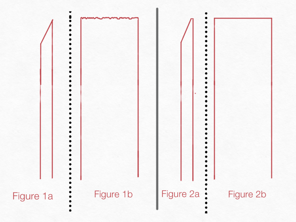
He started by pointing out that when sharpening a blade to a fine edge, as in Figure 1a, there comes a point when the metal is so thin it has no structural support.  In other words at the finest point where 2 planes of a piece of metal converge it is at places only 1 grain of metal thick and it is not consistent since even when using a very fine grit abrasive the grit of the abrasive is larger than the metal grains.  The product of this process, if looked at under extreme magnification would look like the drawing in Figure 1b, and the edge so thin it would be fragile.  While it would cut, or actually saw, and appear sharp it would dull quickly as some of the edge brakes off and other portions bend over.  If fact when we use a sharpening steel to sharpen a blade, we actually aren’t sharpening it, but realigning the metal at the edge. With this process it doesn’t take very long before the blade is dull beyond the point of recovery.

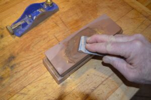
Polishing the back of a blade

Polishing the back of a blade

In reality what we want to produce when sharpening a blade is not 2 planes converging, but 2 planes coming very close to converging then being joined by a 3rd plane that is the minimum thickness to keep the 2 planes from converging while remaining to maintain the stability of the metal’s lattice structure.  This is best illustrated by the drawing in Figure 2a and the benefits and stability are illustrated by the drawing in Figure 2b.  When you are able to achieve this configuration on a blade, it will cut smooth and remain sharp.

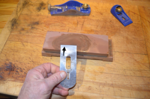
Evidence that the back is flat

Evidence that the back is flat

Great theory, but how do you get there?  Well, he showed me and I’ll describe it as best I can, using a single bevel plane blade as an example.  This process works on bi-bevel blades such as knives too, but requires some adjustments in technique.

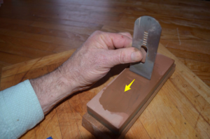
Start by polishing the back side of the plane blade first to insure that it is flat.  This is done by laying it back side down on a stone and working it until it has an even patina of abrasion from edge to edge.  Next you will work the bevel, to do this you will need a guide to maintain a perfect angle while sharpening, I don’t believe anyone is able to hold it freehand precisely enough to meet the goal of creating a precision edge.  Repeat this process, backside then front, until you are at the finest grit stone you will be sharpening with.  While working with the last grit on the bevel polish it until you raise a burr all along the back side of the blade, then take the blade while holding it with the point resting on the stone and drag it smoothly about 1 inch, you just made your 3rd plane.  Next, polish the bevel on the stone counting the strokes, checking for the burr to be raised again after each stroke.  Once you get a burr again, hold the blade with the point on the stone and duplicate the drag you did previously.  Now polish the blade one more time counting the strokes, but with 2 to 4 less strokes and you have a sharp blade that will maintain its edge.

Draw the blade back 1 inch

Draw the blade back 1 inch

A few details to be aware of:

  • Insure your stones are flat.  If you are using water stones they will develop a shape with use that you will need to addressed by flattening them.
  • Use a 3 point guide so the blade will define its own cant.

Lastly, its been about 20 years since I had this valuable encounter and over the years I lost the contact information of the man that educated me on sharpening.  I’ve tried to find this gentleman again unsuccessfully, but while writing this I searched one more time and I found him on the internet.  The shop’s name is Tashiro Hardware, LLC, of Seattle, Washington and the proprietors name is Frank Tashiro.  On his website tashirohardware.com he notes that he will be 93 in January of 2015 and It appears he is shutting up shop, but hopes to publish a manual on sharpening prior to shutting down his website.  As of this writing he hadn’t published the manual yet, but I hope he does. Based on the education I got in his shop in a couple of hours, having his knowledge preserved in a manual will greatly benefit anyone who is interested in maintaining a sharp blade.

LED Cable Lighting Project

I have been wanting to change the lighting in my house to LED lights. To do it there are a couple of options, replace the standard bulbs with LED conversion bulbs or change the fixtures to low voltage fixtures designed for LEDs, both of which are relatively expensive.  Changing the bulbs in my current fixtures is the simplest method, but I would end up paying a higher cost for the bulbs and wouldn’t get some of the lighting benefits available from standard LED bulbs.  Replacing all of the fixtures with fixtures designed for LEDs would allow access to the lower prices bulbs and the more flexibility, but would entail more work and the purchase of the fixtures which seem to be sold at a premium price .

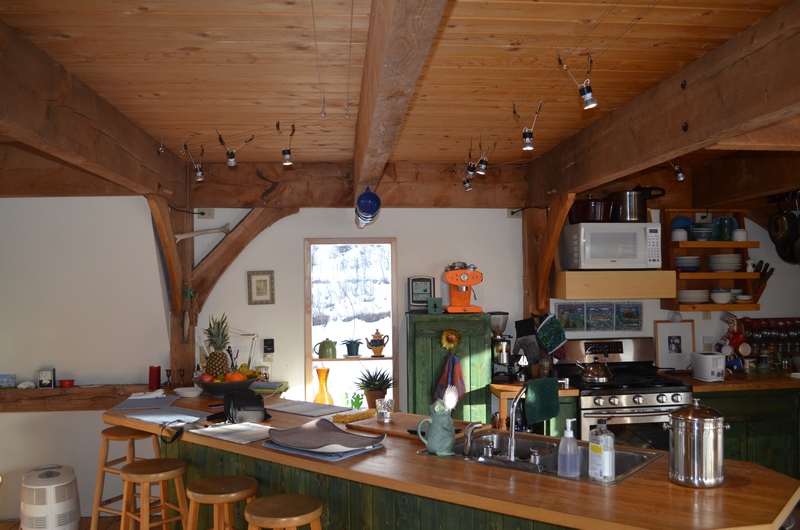
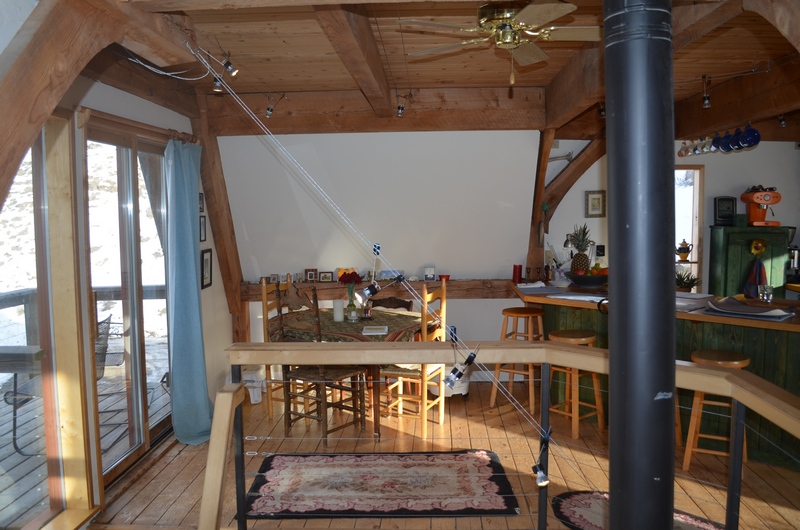
Lights installed in my kitchen

Lights installed in my kitchen

These issues led me to evaluate building a system from available parts, which it turns out are relatively inexpensive.  The parts I needed to make this functional in my home were a support structure, a 12 volt power supply and a fixture to connect the bulb to the system.

Cable and Transformer

Cable and Transformer

For the support system I used 3/32″ steel cable which could be stretched with turn buckles and strung in parallel runs where I wanted the lighting.  Since the lighting is low voltage there is no hazard running the current through the uninsulated cable.  I attached the cable to the ceiling or walls with eye bolts and maintained a 4″ spacing between the Parallel runs.

For the Power supply I was able to find 80 watt 12 volt transformers for each circuit.  These are available online for between $12 and $40 dollars apiece with many different wattage outputs.  I chose the 80 watt since it allowed me to place about 10 lights on a circuit with a 20 watt buffer.  I connected the power supply leads to the cables with split nuts.

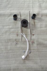
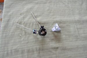
Light Fixture parts, ready for assembly.

Light Fixture parts, ready for assembly.

The light fixtures took a little more work.  I wanted a fixture that looked good, was easily adjustable and could accommodate different light bulbs based on my needs.  The bulb I choose was an MR16 bi-pin bulb, since they come in spots, floods and different light spectrum outputs.

The raw parts I used for the fixtures were as follows:

  • 1/8″ Stainless Steel TIG rod for the fixture extensions, this comes in 3′ lengths and cost about $1.25 per stick.
  • 1 1/2″ machinable plastic rod for the insulator, it comes in 1′ sticks for $6.00.
  • MR-16 Lamp holders, 11 in the pack for $5.00
  • 1/8″ shaft collars, $1.50 each
  • #4 X 3/8″ screws, $0.03 each.
  • 10-12 Parallel crimp connectors, $3.00 per package of 20.
  • The spring out of a broken tape measure to be fashioned into a retaining clip.
  • 6 watt 500 lumen MR 16 LED Floods, $5.00 each.

I started making the insulator by cutting the plastic rod into 7/8″ long pieces, then using a 1/2″ Forstner bit to drill a hole in the center of the plastic disk 7/16″ deep.  Then I used a  9/32″ bit to drill the rest of the way through the disk.  I finished the insulator by drilling an 9/64″ hole on each side of the disk.

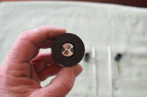
Insulator with Lamp holder installed

Insulator with Lamp holder installed

At this point the lamp holder will fit into the hole in the insulator that was made by the Forstner bit and the wiring will go through the 9/32″ hole.  I used 2 – #4 X 3/8″ screws to fasten the lamp holder to the insulator.

I cut 2 pieces of 1/8″ stainless steel rod 7″ long and rounded the ends on a grinder.

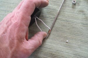
I left about 2″ of wire on the lamp holder and striped it baring about 3/8″ of wire.  Then fed the striped piece of wire into the 10-12 Parallel crimp connector and forced the 7″ long stainless steel rode in after it.  Depending on the brand of connector this may be a good tight fit, but on some connectors it is loose.

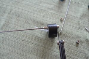
Sliding rod into connector with striped wire

Sliding rod into connector with striped wire

The rod is then slide through one of the 9/64″ holes in the insulator and a 1/8″ shaft collar is used to secure it.  The same process was used for the other rod and wire.  Once both rods and wires were connected I secured the wires by crimping.  I finished with the rods by bending them away from each other until the span between them was approximately 5″ at the top.

Securing shaft collar to rod

Securing shaft collar to rod

The last thing necessary prior to plugging in the bulb was to make the retaining clips.  These were made from the spring out of a broken tape measure.  The spring cuts easily with a pair of tin snips, so I cut it into pieces about 2″ long and dog eared the corners so they wouldn’t be so sharp.  The tricky part is putting the holes in them so they will go over the rods.  If you try to drill them, they will break and may cut you in the process.  The way I found to get the holes in them was with an old paper hole punch.  It has to be one that can handle a pretty large stack of paper to have the right configuration.  Once I found one that would work, making the holes was easy.  I put a hole in each end of the clip.

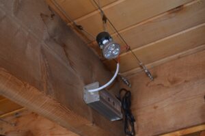
Assembled lamp and bulb

Assembled lamp and bulb

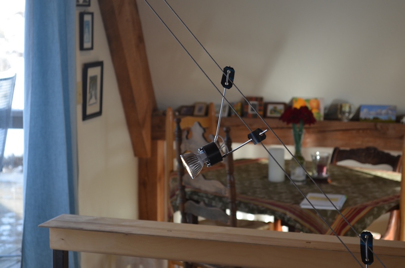
The clips will be shaped like a “C” since they are spring steel, I slid the rod through the hole in the top of the “C”.  Place the rods between the cables and bend the clip over the cable so it is trapped between the rod and the clip, then slip the second hole in the clip over the top of the rod.  To adjust just squeeze the clip together and slide it up or down.

Creative cabling to get light where I wanted it

Creative cabling to get light where I wanted it

Close up of a light

Close up of a light

Longer rods

Longer rods