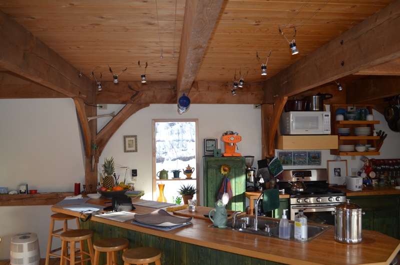
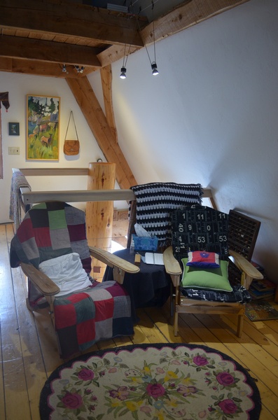
I have been wanting to change the lighting in my house to LED lights. To do it there are a couple of options, replace the standard bulbs with LED conversion bulbs or change the fixtures to low voltage fixtures designed for LEDs, both of which are relatively expensive. Changing the bulbs in my current fixtures is the simplest method, but I would end up paying a higher cost for the bulbs and wouldn’t get some of the lighting benefits available from standard LED bulbs. Replacing all of the fixtures with fixtures designed for LEDs would allow access to the lower prices bulbs and the more flexibility, but would entail more work and the purchase of the fixtures which seem to be sold at a premium price .
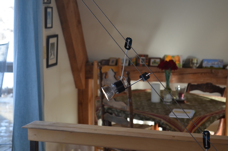
These issues led me to evaluate building a system from available parts, which it turns out are relatively inexpensive. The parts I needed to make this functional in my home were a support structure, a 12 volt power supply and a fixture to connect the bulb to the system.
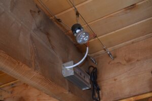
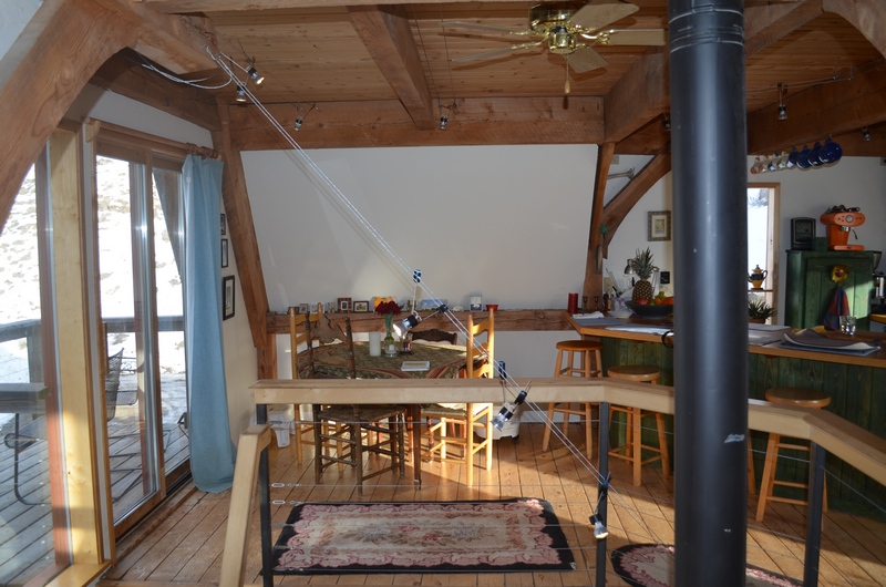
For the support system I used 3/32″ steel cable which could be stretched with turn buckles and strung in parallel runs where I wanted the lighting. Since the lighting is low voltage there is no hazard running the current through the uninsulated cable. I attached the cable to the ceiling or walls with eye bolts and maintained a 4″ spacing between the Parallel runs.
For the Power supply I was able to find 80 watt 12 volt transformers for each circuit. These are available online for between $12 and $40 dollars apiece with many different wattage outputs. I chose the 80 watt since it allowed me to place about 10 lights on a circuit with a 20 watt buffer. I connected the power supply leads to the cables with split nuts.
The light fixtures took a little more work. I wanted a fixture that looked good, was easily adjustable and could accommodate different light bulbs based on my needs. The bulb I choose was an MR16 bi-pin bulb, since they come in spots, floods and different light spectrum outputs.
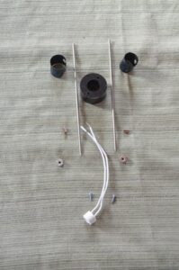
The raw parts I used for the fixtures were as follows:
- 1/8″ Stainless Steel TIG rod for the fixture extensions, this comes in 3′ lengths and cost about $1.25 per stick.
- 1 1/2″ machinable plastic rod for the insulator, it comes in 1′ sticks for $6.00.
- MR-16 Lamp holders, 11 in the pack for $5.00
- 1/8″ shaft collars, $1.50 each
- #4 X 3/8″ screws, $0.03 each.
- 10-12 Parallel crimp connectors, $3.00 per package of 20.
- The spring out of a broken tape measure to be fashioned into a retaining clip.
- 6 watt 500 lumen MR 16 LED Floods, $5.00 each.
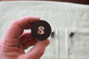
I started making the insulator by cutting the plastic rod into 7/8″ long pieces, then using a 1/2″ Forstner bit to drill a hole in the center of the plastic disk 7/16″ deep. Then I used a 9/32″ bit to drill the rest of the way through the disk. I finished the insulator by drilling an 9/64″ hole on each side of the disk.
At this point the lamp holder will fit into the hole in the insulator that was made by the Forstner bit and the wiring will go through the 9/32″ hole. I used 2 – #4 X 3/8″ screws to fasten the lamp holder to the insulator.
I cut 2 pieces of 1/8″ stainless steel rod 7″ long and rounded the ends on a grinder.
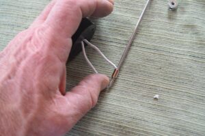
I left about 2″ of wire on the lamp holder and striped it baring about 3/8″ of wire. Then fed the striped piece of wire into the 10-12 Parallel crimp connector and forced the 7″ long stainless steel rode in after it. Depending on the brand of connector this may be a good tight fit, but on some connectors it is loose.
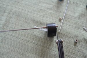
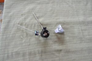
The rod is then slide through one of the 9/64″ holes in the insulator and a 1/8″ shaft collar is used to secure it. The same process was used for the other rod and wire. Once both rods and wires were connected I secured the wires by crimping. I finished with the rods by bending them away from each other until the span between them was approximately 5″ at the top.
The last thing necessary prior to plugging in the bulb was to make the retaining clips. These were made from the spring out of a broken tape measure. The spring cuts easily with a pair of tin snips, so I cut it into pieces about 2″ long and dog eared the corners so they wouldn’t be so sharp. The tricky part is putting the holes in them so they will go over the rods. If you try to drill them, they will break and may cut you in the process. The way I found to get the holes in them was with an old paper hole punch. It has to be one that can handle a pretty large stack of paper to have the right configuration. Once I found one that would work, making the holes was easy. I put a hole in each end of the clip.
The clips will be shaped like a “C” since they are spring steel, I slid the rod through the hole in the top of the “C”. Place the rods between the cables and bend the clip over the cable so it is trapped between the rod and the clip, then slip the second hole in the clip over the top of the rod. To adjust just squeeze the clip together and slide it up or down.


